Wiring
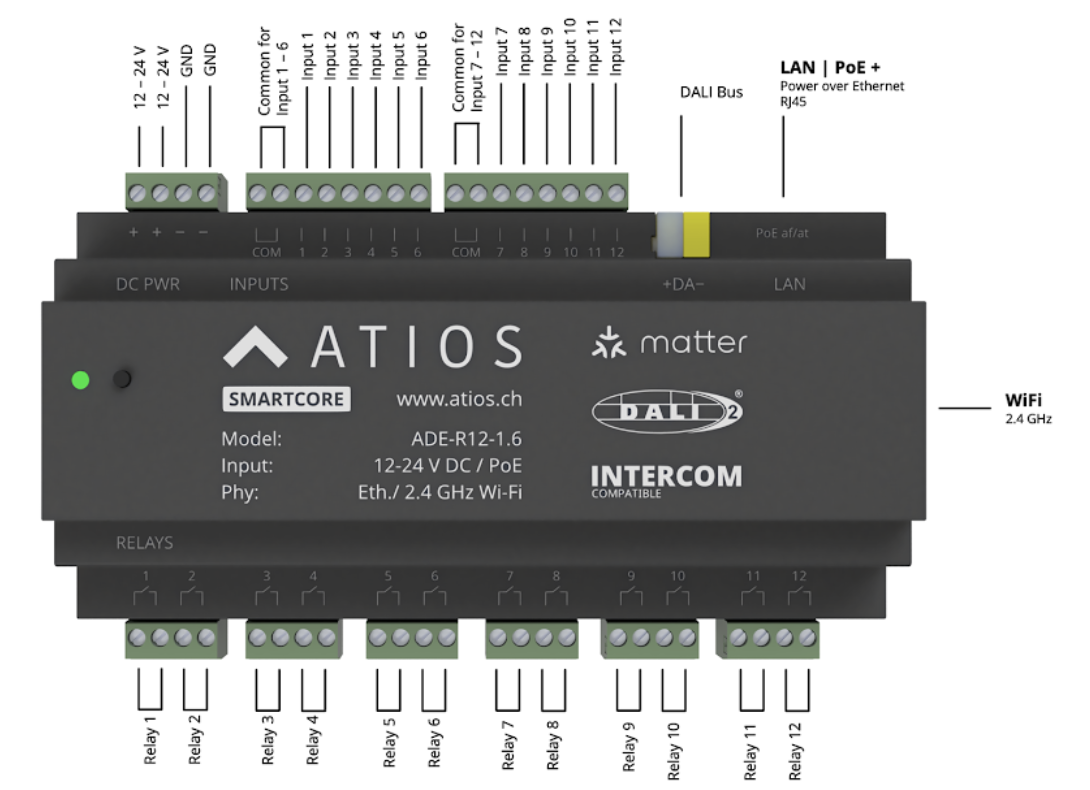
I/O at a glance
| Side | Type | Notes |
|---|---|---|
| 12 relay outputs | Potential-free (dry contact) | Rated 16 A. AC phases and DC voltages can be mixed across relays. |
| 12 digital inputs | Opto-isolated | Sense 12 V DC up to 230 V AC against the COM reference for the input group. |
Inputs and outputs are electrically isolated from each other. They do not need to share a breaker, neutral, or supply.
230V Loads
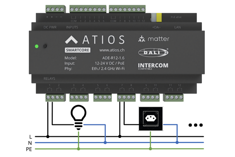
Each of the 12 relays has potential free contacts rated for 16 A. AC phases and voltages can be mixed when connecting 230V loads to the relay outputs.
TIP
Potential free contacts allow maximum flexibility in load connection. Multiple phases and voltage sources can be used across different relays.
24V Loads
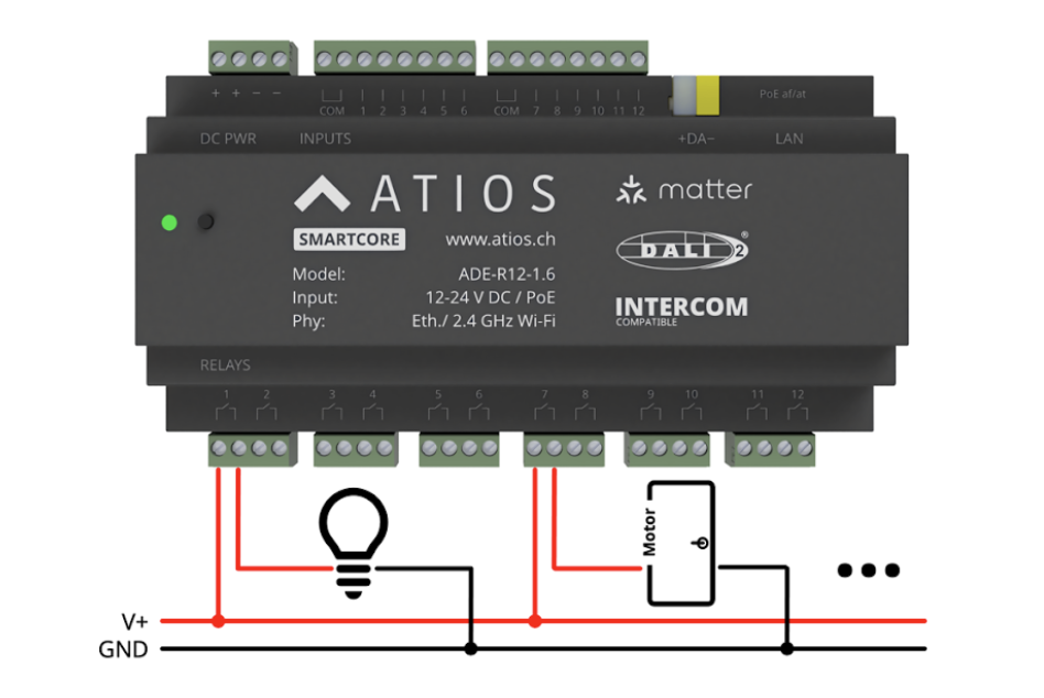
Each of the 12 relays has potential free contacts rated for 16 A. AC phases and voltages can be mixed when connecting 24V loads to the relay outputs.
Window Covering
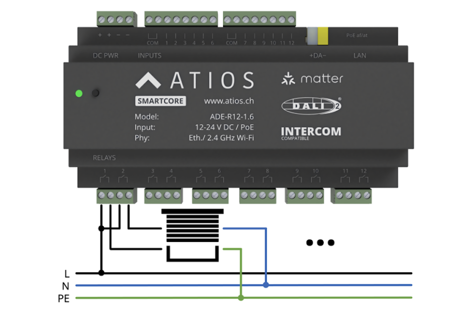
Each of the 12 relays has potential free contacts rated for 16 A. For window covering motors, the supply phase must be connected to each relay used for the up and down directions.
Mixing circuits, phases and voltages
Inputs and outputs are electrically isolated from each other and from the device's power supply. They do not need to share a breaker, neutral, or phase.
In a single SmartCore you can freely combine, for example:
- Relays freely combine voltages: relay 1 on an L1 230 V AC light, relay 2 on an L3 230 V AC blind, relay 3 on a 24 V DC valve
- Inputs and relays can run on different voltages: relays switching 230 V AC while inputs sense 24 V DC dry-contact buttons, or the reverse
- Each relay can sit on its own breaker, no common neutral required
The only mixing rule is within an input group: inputs 1–6 share one COM reference, inputs 7–12 share another. Use the same voltage type (all DC or all AC) within each group, and keep both groups on the same voltage type.
Inputs and 24V Power Supply
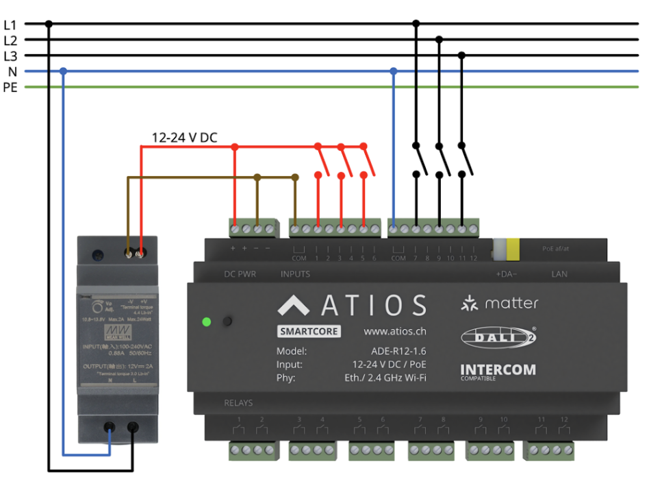
When using an external 24V power supply with the SmartCore:
- Do not connect the device simultaneously to both Power over Ethernet and external DC power
- All 12 inputs are opto-isolated and require a reference connected to the COM terminal
- Inputs 1 to 6 share one reference terminal
- Inputs 7 to 12 share a separate reference terminal
- Inputs detect voltages from 12 V DC up to 230 V AC
WARNING
Both input groups (1-6 and 7-12) must use the same voltage type. Within each group, use either DC or AC, not both.
DC Inputs
For DC inputs, connect the reference voltage to GND.
AC Inputs
For AC inputs, connect the reference to neutral. Phases L1 to L3 can be mixed since the current flow is minimal (maximum 2 mA).
Powering inputs from PoE
When the SmartCore is powered via PoE, the device exposes its internal +12 V and GND rails on the input terminal block. You can use these to source the dry-contact reference for the input groups instead of installing a separate 12–24 V DC supply.
Typical use: tie the input group's COM to GND and wire each external switch between +12 V and the input terminal.
WARNING
Do not also connect an external 12–24 V DC supply to the SmartCore's power terminal when running on PoE. Power the device from PoE or the DC terminal, never both.
Wiring an external switch
To read a wall switch or push button, wire the switch across the input terminal and the matching COM reference for that input group. The reference can be:
- A 12–24 V DC supply (typical when the SmartCore is powered via PoE, see Powering inputs from PoE)
- A neutral (N) when sensing AC line-driven switches
Both ends of the switch are passive. No mains is exposed at the switch unless you intentionally wire AC to the input.
DALI
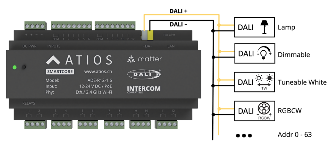
The SmartCore can be connected to a DALI Bus for communication with DALI-2 devices.
Power Supply Options
The DALI Bus can be powered in two ways:
- External power supply - Use a dedicated DALI power supply
- Integrated DALI power supply - Use the SmartCore's built-in DALI power supply
WARNING
Only use one power supply method at a time. Do not use both external and integrated power supplies simultaneously.
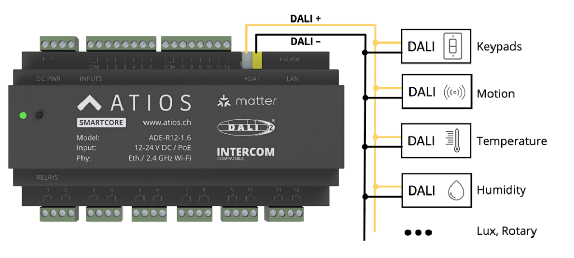
DALI-2 Master Controller
The SmartCore acts as a DALI-2 Master Controller and can receive events from connected DALI-2 sensors in instance mode.